BCT:  Automatic machining of individual parts/Adaptive Machining

During tool and mold construction, as well as during the manufacture and repair of aero-engine components, the real machining strategy differs from the previously planned approach. Parts are not clamped in the foreseen position and with the foreseen orientation – or they display individual differences in shape caused, for example, by production-related fluctuations or wear during operational use. Taking account of these deviations usually requires complicated manual machining. This does not have to be the case!
BCT solutions capture the position and shape of each individual workpiece prior to machining and transfer a predefined strategy to these parts. They do this separately for each part but nevertheless in an automated manner! We call this approach Adaptive Machining.  Learn more about AM developments, applications and solutions. Ask us how we can solve your problems!

Your Advantages:

+ consider individual part shapes, automatically
+ avoid a long and complicated manual setting-up process.
+ reduce the requirements for the fixture, which in turn lowers costs.
+ lower the number of rejects.
+ miminise manual rework.

OpenARMS_850

OpenARMS, tool for Adaptive Machining

BCT’s system OpenARMS (Open Adaptive Repair and Manufacturing Software) is employed in situations where the individual shape of parts – as well as varying clamping positions – have to be taken into account. The integration of different CAD and NC formats permits smooth cooperation with customer-specific systems. OpenARMS can be connected to various NC controls and the integrated measurement module supports both tactile and optical sensors. Based on information on the current part, geometric adaptation of the manufacturing program is undertaken. During this process, the specifications are automatically transferred to every single individually-shaped part. The close connection to NC machines makes it possible to carry out automatic processing – similar to series manufacturing – despite differences between the individual parts.

OpenARMS is the link between the CAD/CAM description of the part and the real individual parts. This adaptation is not limited to special manufacturing methods. When turbine blades are milled or ground, for example, the adaptation of the machining paths makes the laser powder fusion welding process more precise. During the processing of carbon-fiber composite parts, OpenARMS permits targeted material removal on each single, individually shaped part as a preliminary step prior to repair.

Learn more about developments, applications and solutions in our brochure – or test us!

Your advantages:

+ Taking account of the individual shape and position of the parts
+ Integrated capture of part shape and position via either optical or tactile sensors
+ Automated machining via direct connection to the machine centers
+ Adherence to tight tolerances even for individual shapes

Triebwerk_grau

Fan
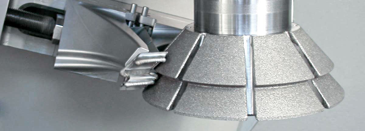
New part: During the final machining of forged blades, snubbers are milled in accordance with the nominal geometry: a gentle transition to the blade surfaces is achieved by adaptation. Other applications include profiling of leading and trailing edges and machining of the platform.
Repair: Recontouring of the leading edge

Compressor
New part: Final machining of linear-friction-welded blisks
Repair: Recontouring of welded-on or patched tips or leading and trailing edges Fusion welding for tip repair

Combustion chamber
Repair: During repair of cracks, adaptive systems help to automate complex repairs and welding processes. Suitable strategies are selected here independently of the extent of the damage.

Turbine 
Repair: During a tip repair, OpenARMS captures the individual shape and position of the particular blade and takes it into account during the subsequent reprofiling by milling or grinding. See system integration.
Repair: Here OpenARMS supports the welding process carried out to reconstruct the seal profile in the tip region.

Turbine stator vanes
Repair: High loads cause a change in the blade profile. Following a previous soldering process, adaptive machining allows for automated reprofiling and thus the restoration of aero-engine capacity.

Blisk manufacturing
New part: OpenARMS removes the retaining elements needed during friction welding of blisks and creates a gentle transition to the annular space. The complete work sequence (measurement, calculation, performance) is monitored by OpenARMS.

DSC_2676_RET_850

Reworking of printed parts
After “printing,” functional surfaces, drillings and other functional elements are created via subtractive methods (such as milling) and the supporting structures required for the construction process are removed. Despite production-related geometrical fluctuations, adaptation allows for gentle transitions between the individual sectors.

Hybrid machining
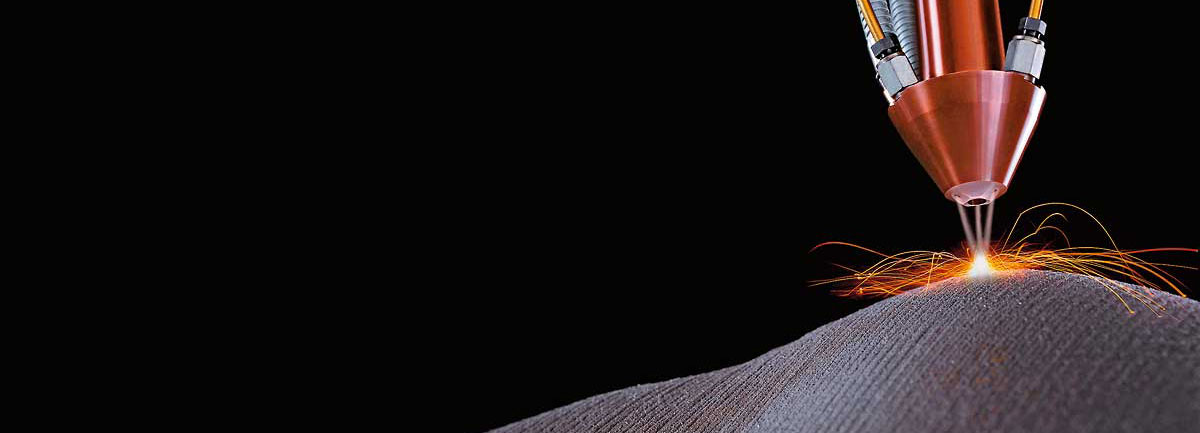
Hybrid manufacturing methods within one machine constitute current application areas for adaptive machining, which in this context supports both laser material deposition (LMD) and subsequent reprofiling via milling or grinding. The deposition or addition of special functional elements to basic parts via laser fusion welding (mass customization) is another application.

Hybride maschines
During the repair of turbochargers, OpenARMS monitors the combination of additive and subtractive processes (hybrid). After the damage is removed by milling, the damaged areas are filled in with material by the same machine and subsequently reworked.

Moreover, local repairs can be performed on worn tools in the same way. Damaged areas are removed and preparations made for material deposition. Following material deposition, a milling process is used to restore the desired geometry.

composites

New part: Geometrical deviations cause problems during many steps in composite manufacturing. Automation with conventional NC processes runs up against its limits here. However, these tasks can be mastered by geometrically adaptive machining.

In comparison with the relatively simple assembly of metallic components, the assembly of composite parts is more complicated, owing to their larger dimensions and deviations in shape. In the process the size of the components increases steadily. Because of the simultaneous tightening of the tolerances, geometrically adaptive machining is becoming increasingly important.

Adaptive remilling of parts with overmeasures (sacrificial machining) and the post-machining of contact surfaces to reduce the effort required during the subsequent shimming are typical applications of OpenARMS-PostM.

Repair: Carbon-fiber parts frequently display individual shapes or damage requiring the removal of large areas (scarfing). Carrying out this work by hand is very burdensome. Preparations for a repair can be made automatically via adaptive machining: the part is first scanned and the results are used to adapt the machining strategy.

OA_850
Adaptive Machining with OpenARMS: The BCT solution for taking account of individual part shapes

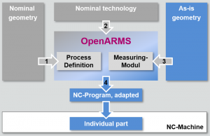
In contrast to classical manufacturing, adaptive machining takes account of the individual shape of the particular parts in addition to the particular clamping situation. BCT’s systems thus achieve the automatic machining of individual parts. Adaptive machining presupposes knowledge of the nominal situation and the current real situation. The difference between the two serves as an input for calculating an adaptive machining strategy.

The nominal state is usually defined in the CAD/CAM system (1/2). CAD/NC interfaces are available for importing. The openness of the BCT system allows for cooperation with different CAD/CAM systems. Users can always employ the tools most suitable for the particular task.

The actual state (3) is captured either optically or directly by tactile means or measurement values from other systems are read in. The result of the adaptation is an NC program adapted to the position and/or part geometry (4). For automatic machining the BCT solutions can be connected to NC machines or robots with a wide range of controls.

Adaptive machining / adaptive milling optimizes the finishing of forged rough parts, for example. The repair of valuable individually shaped parts (e.g. turbine blades) is made possible in the first place by capturing and taking account of the particular geometry. Caution: the adaption is not limited to special manufacturing methods. Next to milling and grinding, we also support generative methods (3D printing) – for example, by adapting the paths for laser fusion welding. In all applications, however, an NC program defined in advance by the customer and BCT remains the starting point for adaptation.

OpenFIT_heller_840w2

OpenFIT

During the manufacturing of parts, the exact alignment often presents some challenges. These problems may be caused by production-related part deviations, simple fixtures or differences in their handling:
– Nevertheless, machining of the part must take place in the planned position.
– Nevertheless allowance has to be considered when processing casted or printed blank parts to “fit” the final geometry into the blank part.
Additionally the solution should:
– not require using the CAD/CAM systems, again
– adopt the previously defined and tested NC programs
– take characteristics of machine and fixture into account

OpenFIT will solve such or similar processing tasks.
In a first step CAD model of part and fixture as well as the manufacturing program will be imported.
Definition and execution of the measurements to capture the position of the parts inside the machine are realised using the integrated measuring module (tactile probing). Direct communication with the NC controller enables the automatic transfer of measuring programs and results.
Based on this, OpenFIT adapts the position/orientation of a planned machining sequence in minimising the deviations. There is a choice to adapt the NC program, directly or – more elegant – just to transfer the description of the new working coordinate system to the controller. In this case the NC program remains unchanged! The adjustment will only change the orientation in which it is carried out.

OpenFIT_2_e_small

Using the functionality of option BestFIT position and orientation of the process are adjusted.

With the extended function of option VolumeFIT, allowances are taken into account as well. This guarantees, that appropriate allowances are available to realise reliable processing of the parts.
Datasheet

Your Advantages:

+ A complicated manual alignment process is no longer necessary.
+ The requirements for the fixture are reduced, thereby lowering costs.
+ You have control over the machining overmeasure (VolumeFit).
+ The program can be easily integrated into the present process workflow.

Compensation of clamping mistakes
Serial parts clamped in a simple fixture exhibit differences in orientation. The position of the part is measured. The NC programs are either adapted directly or implemented in unchanged (!) form within a new coordinate system on the machine.

Reworking of 3D printed parts
Drillings, fits and functional surfaces are created, after the actual printing, via classical manufacturing methods such as milling or drilling. To achieve the correct orientation during machining procedures, the position of the part inside the NC machine is measured. To increase accuracy, the compensation also takes account of the degree of freedom of the fixture.

Reworking cast parts
On larger cast parts, flanges etc. are to be machined. For this purpose, the position of the part as well as the local overmeasure at the machining points is taken into account. The information on position and overmeasures is obtained either by direct measurement in the machine or via the import of measurement data from external sources.

OpenScan_1

OpenSCAN

To be able to take account of individually shaped parts or special clamping situations within the scope of adaptive machining, we first have to determine the differences between the actual situation and the nominal situation (CAD). All adaptive systems either come with integrated measurement devices – or are connected to such devices – for this purpose.
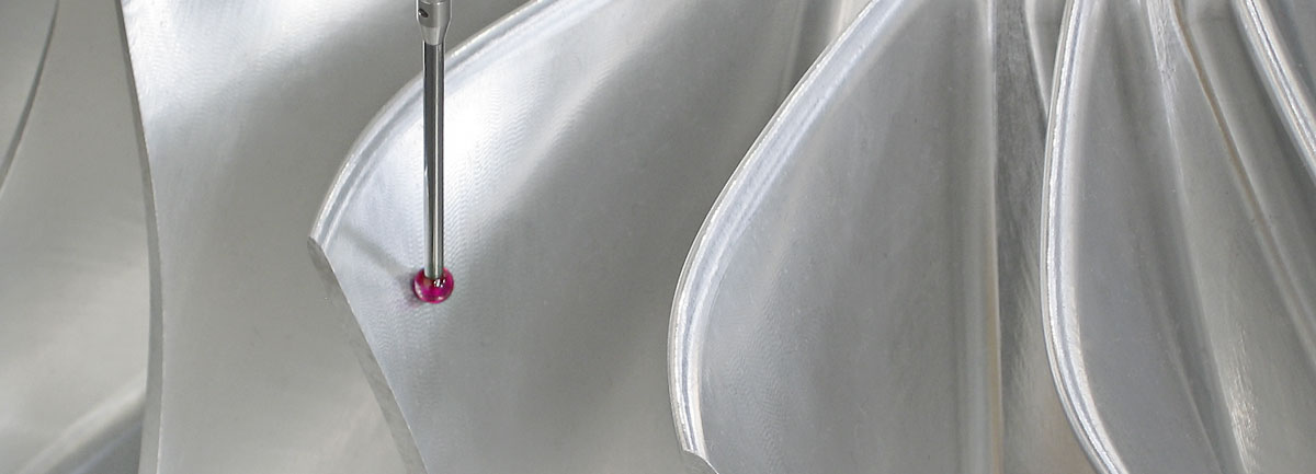
In the simplest case, the differences can be determined with touch trigger probes. In most cases, these have already been incorporated in the NC machines by the machinery manufacturer and permit reliable measurement of individual points. The BCT solutions for adaptive machining include integrated measurement modules with which measurement sequences can be defined and results displayed.
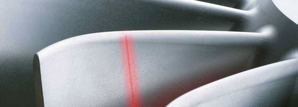
However, if the machining task requires a large number of measurement points, laser line scanning is more suitable. With this method the distances between the sensor and a strip projected onto the part are evaluated point by point. This method is very fast and simultaneously delivers a large number of measurements points. These measurement procedures can be defined with OpenSCAN. The precision of the measurements is increased by special compensations – in particular, when these are undertaken from different directions (OpenSCAN is available for the Sinumerik 840D).
data sheet

Your advantages:

+ Measurement of the part in the machine
+ Short measurement times together with a high resolution
+ Capturing part states for various purposes

Capturing the geometry of carbon-fiber parts
During the scarfing of workpieces made of composite material, individual layers have to be removed in a defined way. Knowledge of the part’s geometry is a basic prerequisite in this context. Area data can be captured quickly and precisely via laser line scanning.

Reprofiling of leading and trailing edges of fan blades 
The actual shapes of the leading and trailing edges are captured in a first process step. Laser line scanning delivers the corresponding data with high accuracy. With the aid of actual data, the software then calculates the NC programs for reconstructing the desired profile.

3D printing
A scan made with a laser line sensor serves to monitor the interim results after the deposition of a certain number of layers during laser fusion welding. The captured state can be used to adapt the subsequent process steps.

BCT_Systemintegration_b

System Integration

Adaptive systems always consist of a combination of measurement technology and NC machines. Automated machining requires the exchange of information and data between individual components. To achieve this, OpenARMS is usually connected directly to the machine center. With this configuration it is possible to transmit measurement programs, receive measurement results, and transmit and run the adapted NC programs. We support the most commonly used control types. Please don’t hesitate to ask us.
In addition to software, BCT supplies the matching sensor technology for capturing the actual geometry, the clamping elements and other elements up to and including the complete systems including the NC machines of your choice.
An application-oriented briefing on the systems ensures their quick and economic use and is thus a matter of course. Users are put in a position to set up their own projects and define their own processes.

Your adavantages:

+ Delivery of the complete system from one source
+ Smooth integration of different components
+ Realisation of complex process workflows

The BCT systems
We deliver complete systems for adaptive machining. Our clientele includes major players in the aerospace overhaul industry such as airlines and manufacturers of gas and steam turbines. During development we rely on a modular concept; as a result, we can realize customer-specific solutions relatively fast.
All installed solutions are coordinated directly with the particular customer and are tailor-made to meet the specific requirements.
Our contacts to machinery and control manufacturers ensure that you receive a solution that is state of the art.

For reasons of confidentiality, we cannot go into greater detail here. We are sure that you would not like to see your solution published on our website. If you are interested in receiving more information, please contact us!

OpenDATA_840_214

OpenDATA

We can only improve a process if you have enough information on it. If we look at a milling process, for example, we see that vibrations, milling forces, rpms and feed can be measured. In the area of laser powder fusion welding, we see that a large number of parameters – ranging from the laser output to the temperature of the melting bath – can be recorded.

With OpenDATA, moreover, we can now answer the question of which values are to be measured – and at which locations – on the part! This local resolution permits a fast and practice-oriented insight into the particular process and thus delivers reliable information for optimization or monitoring.

OpenDATA combines positional information from the machine with measurement values supplied by external sensors.
We will find a solution to your problem as well!

Your advantages:

+ Precise assignment of measurement values to the part itself
+ Support of a wide range of sensors (National Instruments interface)
+ Easily understandable visualization of measurement values

Temperature measurement during laser metal deposition

As part of a project carried out in cooperation with the Institute for Laser Technology (ILT) in Aachen, melting bath temperatures are plotted and assigned to positions on the part. This allows for a deeper insight into the process and opens up new vistas of analysis and evaluation for the researchers – all of which can, in the final analysis, be used to optimize the process.

Laser

OpenLMD

The ability to add material to a base geometry  or to parts in case of repairs (hybrid manufacturing approach) opens up some new manufacturing routes.
During the LMD (Laser Metal Deposition) process material in form of powder is blown into a melt pool generated by a
laser while moving the laser spot along the part. This process generates new geometries layer-by-layer on base parts of unlimited size! Special equipment is available for such processes.

In case that material should be added to an existing part, its geometry is of special interest to calculate the volume which has to be generated by LMD, afterwards.
Therefore the base geometry has to be captured e.g. by optical scanning previous the actual printing process. In the next step the build volume has to be determined and trajectories for the laser have to be calculated (LMD technology characteristics to be considered) and sent to the equipment for execution.
To support the user of such systems, BCT developed the package OpenLMD integrating the above mentioned process steps and fully connected to the equipment. With this the user is able to handle all process steps in on software environment. Direct access to the most relevant parameters in combination with simulation the machine/robot movements helps to check the process settings.
data sheet

Your advantages:

+ One software combining measuring, process flow and LMD path generation
+ LMD on dedicated machines and robots
+ Add geometries even to curved substrates!

Mass customisation

Based on a “standard” base part, components can be manufactured depending on the special needs. E.g. individual elements can be added to a base part manufactured in a traditional way. In the same way component’s performance can be improved by adding extra material to regions where it is needed and so to meet the higher requirements.